
A requirements tree is a useful tool especially for software and project managers, and is common within groups using the Agile methodology. Not only does a requirements tree provide a visual representation of a software program’s functionality, allowing for easier organization and communication, it also helps to identify any potential risks or problems that could arise in development. Breaking down the project into smaller components allows stakeholders to gain insight on what is required to move the project forward, and identify dependencies across requirements. Additionally, breaking down the software into its most basic components allows for easier maintenance, as managers can create changes incrementally rather than all at once. These trees are also very effective at keeping a project in line with its end goals through the entire developmental process. Keep reading to learn how to make one.
Transcript continues after video.
Flying Logic Setup
Users usually read a requirements tree from top to bottom. However, the Orientation of a Flying Logic document refers to the direction of the edges. So, even though we read the tree downwards, the edges flow upwards. The Orientation should then be set to Bottom to Top.
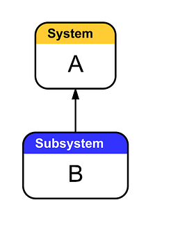
To illustrate, the example above are the first two entities in a tree. Entity A was added first, followed by Entity B. However, the edge flows from Entity B to Entity A. When oriented this way, the tree can be read in the direction of the edges as, “B is a requirement for A to be complete.”
Like any tree, the orientation can be any of the linear options. However, keep in mind that the edges have to flow in the opposite direction to how one reads the tree. For example, if you’re working from left to right, the orientation will be Right to Left.
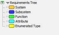
There is no industry standard for labeling requirements, so the domain we use is an example we’ve created. Our domain uses the following entities:
- System: This is the overarching project that the tree visualizes and breaks down.
- Subsystem: These are the largest requirements of the system.
- Function: These are functions that are performed throughout the system.
- Attribute: These are specific types of attributes that fall under a single umbrella. For example, our system allows for use of multiple languages, an Attribute entity would represent a single, specific language.
- Enumerated Type: These are features of the system. They break down into Attributes.
You can access our example domain in this post on Flying Logic’s discussion forum. The first file, Requirements Tree Domain.xlogicd, will open a blank document already containing our example domain.
This domain may not work for your tree, as you may be working on a project that has different requirements than our example does. In this case, you can download and edit the example domain, or create your own domain.
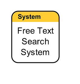
Step 1: Determine the Project
The first step in creating a requirements tree is to determine what the overall project will be. Every requirement tree has a singular project, which is the root of the tree. In our case, we are outlining the requirements for a text search system. Yours may be something different, such as creating an app or building a website. Whatever the case, it’s helpful to know and document what the process is to help stay on track while building the tree.
To add this entity to the canvas, simply drag a system entity (or whichever entity will represent your project) onto the canvas, and label it with a clear description of the project or system.
Step 2: Identify Epics
The next step is to break down the overall project into its largest components. Our example labels these with subsystem entities. Agile methodology calls these Epics. In cases specific to software development, Epics reference a large user story, which breaks down into smaller, more accomplish-able stories. In other cases, Epics may instead reference any feature of a project that contains multiple smaller features.
To add these to your tree , simply drag and drop the relevant entities onto the canvas, either into the drop zone at the bottom of the project’s entity, or onto the canvas to connect them manually.
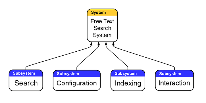
Again, even though adding the entities builds the tree downwards, the edges will flow upwards. All of these requirements go into creating the overall project. Edges automatically orient themselves when dropped in their applicable drop zone. However, if you add entities to the canvas and they don’t automatically connect, ensure that you drag an edge from the subsystem to the system, or from the requirement to the entity that requires it.
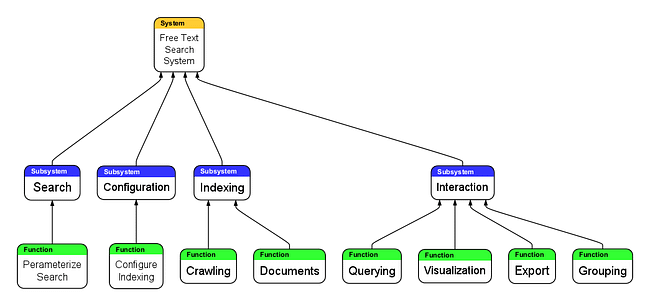
Step 3: Break Down the Tree into Further Requirements
Now, we break down the Epics we’ve already listed into their respective requirements, or stories. For our tree, this means breaking down the subsystem entities into their separate function entities.
When brainstorming functions it can be helpful to focus solely on the Epic they fall under, instead of thinking about the rest of the system at once. Work on one Epic at a time.
Build the tree through the same steps listed above, by dragging and dropping entities onto the canvas. This is how our tree looks at this stage of the process:
Step 4: Continue Building the Tree
From here, all that’s left to do is continue building the tree. The stories we listed last step will break down into their own functions/enumerated types. The requirements making up stories are referred to as tasks.
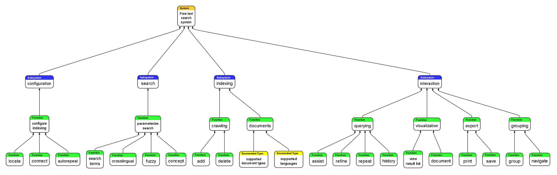
Enumerated type entities should break down into their respective attributes, and functions may break down further.
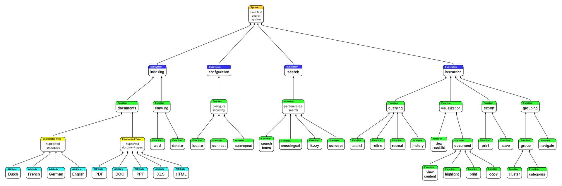
Your tree may have tasks that are required in two different places on the tree. While it is possible to list the same entity twice on a tree, it’s easier to add two edges sprouting from the relevant entity. In our example, the “Supported Languages” entity is applicable to both the “Crosslingual” and “Documents” function entities. So, instead of creating two of the same entity, we’ve created a separate edge leading from the “Supported Language” entity to both of the entities that require it.
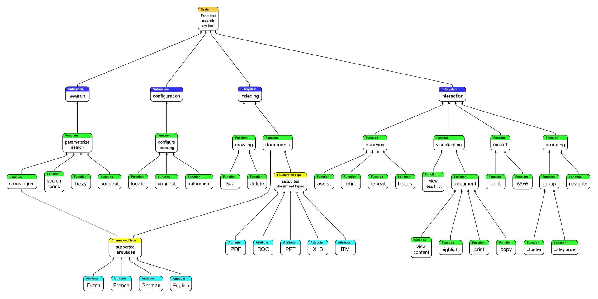
Our tree stops here. Your tree may break down further, so continue this process until there are no more requirements to list. Once all stakeholders are satisfied with the listed requirements, move on to editing and clarifying the tree.
Step 5: Trim the Tree
Start trimming the tree by running through it in your head. Make sure the tree isn’t missing any requirements, or if there are unnecessary or redundant requirements listed. You can also check if the requirements are labeled in a clear and understandable way for other stakeholders.
It’s useful to consult another person while clarifying a tree. A common way to check for clarity is to have another person read it, and get feedback from a fresh set of eyes. You could also have another person read the tree to you, as mistakes that are missed while creating the tree can be highlighted when read aloud. After all stakeholders are satisfied with the clarity of the tree, it is ready to be used and shared amongst users.
What’s Next?
Wanting to do more with Flying Logic? Check out these articles next:
How to Create a Decision Tree with Flying Logic