
Perhaps you have a system you want to improve, and you’ve done a Current Reality Tree to identify what needs to change. Perhaps you’ve also done one or more Clouds to create some potential win-win solutions, in other words what to change to. But…
- How can you be confident which of those ideas will work?
- How do you pick one idea over another?
- How do you know something important hasn’t been ignored or overlooked?
- What are the solution’s strengths, and how can they be maximized?
- How can you be confident the “solution” won’t have unanticipated effects that leave you in a situation that’s worse than before?
- Are a potential solution’s shortcomings something we can live with, something we can fix after the fact, or something we should avoid at all costs?
It is the job of the Future Reality Tree (FRT) to help you answer these questions.
Transcript continues after video.
The FRT is easiest-understood by contrasting it with the Current Reality Tree (CRT):
- To build a CRT, start with a set of Un-Desirable Effects (UDEs), and build down to the Core Driver, from which we invent Solutions (also called injections.)
- To build a FRT, start with a potential Solution (injection), and build upwards to a set of Desirable Effects (DEs).
FRTs can be built not only from a previously-conceived Solution, but also from other parts of previously-created CRTs and Clouds.
Flying Logic Setup
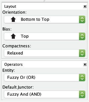
An FRT is based on Sufficient Cause Thinking, and this is how Flying Logic documents are set up when first created, so you do not need to do anything special with the Operators popup menus to start creating your FRT. Most FRTs are drawn with one or more proposed Solutions at the bottom and the Desired Effects at the top, so you may want to use the Orientation popup menu to change the orientation of your document to Bottom to Top.
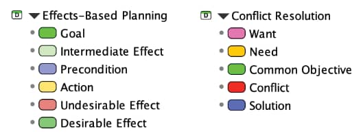
FRTs are created using the entity classes in the built-in Effects-Based Planning domain, and primarily use the following classes: Desirable Effect, Un-Desirable Effect, Precondition, Intermediate Effect, and Action. If starting with solutions created from a Cloud, then FRTs will also often use the Solution class from the Conflict Resolution domain.
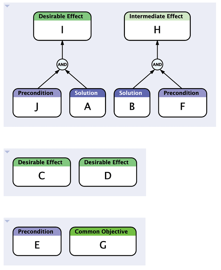
Step 1: State the Proposed Solution and Desired Effects
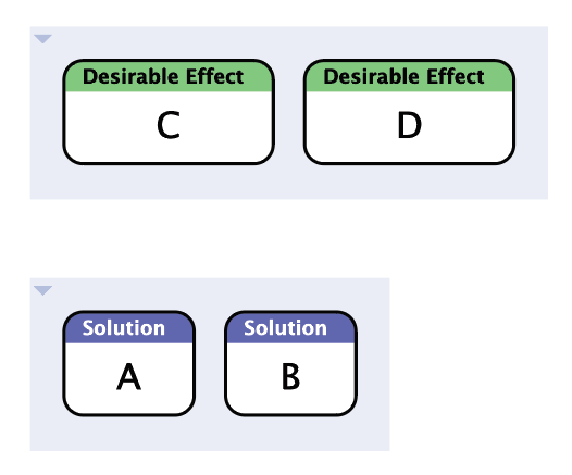
Create one or more Solution entities to identify the set of injections you plan to implement. These injections may come from a Cloud you’ve already created, and you can use the Copy and Paste commands to easily add these entities to your FRT document.
Also create one or more Desirable Effect entities that summarize the outcome you are working towards.
You may wish to temporarily group these two sets of entities to keep them separate; the purpose of the FRT is to fill in the “middle”.
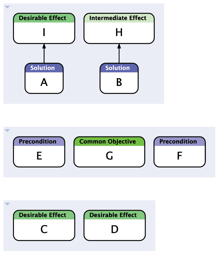
Step 2: Add Other Elements Already Developed
If you have already created a CRT, look for Precondition entities (statements about existing reality) that may be needed in your FRT. You can use the Copy and Paste commands to easily transfer them from your CRT to your FRT.
If you are working from an existing Cloud, also copy over the Common Objective and any of the Needs entities that the proposed Solutions are intended to satisfy.
You may wish to group the entities you’ve added in this step, as they represent entities that will end up in the “middle” of your FRT.

Step 3: Fill In the Gaps
Starting with your Solution entities, add entities that represent the direct, inevitable consequences of those injections being put into place. Use Un-Desirable Effect entities for negative consequences, Desirable Effect entities for positive consequences, and Intermediate Effect entities for neutral consequences.
Use the Categories of Legitimate Reservation, to check your causal connections. If the consequences you add are not sufficient by themselves, then make sure you add any Precondition entities, or tie in any other entities that express the other necessary conditions (AND relationships) needed to produce the predicted result. Feel free to move objects between groups or ungroup the entities when the edges start to give your document structure.
Continue advancing from the effects you’ve identified to additional effects, evaluating whether the subsequent effects are bringing you closer to any of your Desirable Effects, or the Common Objective or Needs entities you may have added from your Cloud. If they do not, continue adding and evaluating effects you may not have previously considered.
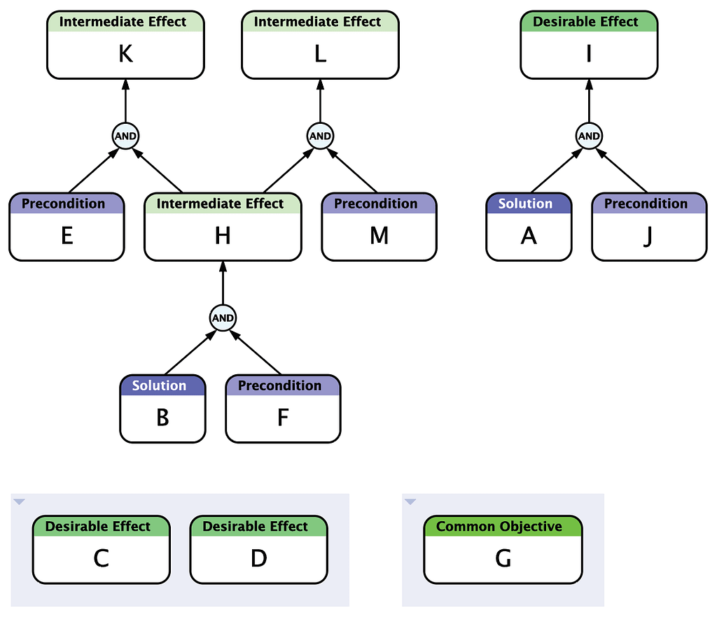
If your progress slows down or stops, then consider additional Action entities you might add. These Actions are also injections, but to differentiate these injections from those that are part of your original solution, use the Action entity class instead of the Solution entity class you started with.
Step 4: Read and Verify the Tree
Once you have made connections to all of your Desirable Effects, re-read the entire diagram. Remember that FRTs are created using Sufficient Cause thinking, so the basic pattern you will use when reading is:
- If cause A then effect B.
When two or more arrows enter an entity, we have multiple sufficient conditions, also called an OR relationship:
- If cause B or cause C then effect D.
When two or more arrows enter an AND junctor, then we have multiple necessary conditions:
- If cause E and cause F then effect G.
Pay careful attention to the Categories of Legitimate Reservation. Make sure every statement in your entities and those implied by the causal relationships are clear and logical.
When reading through the diagram, it is also a good idea to display the Confidence Spinners and use them as an aid to check your logic.
1.Display the Confidence Spinners by clicking the Confidence button in the toolbar or selecting the View ⇐ Confidence command
2.Set every spinner to indeterminate by using the Entity ⇐ Reset Confidence command.
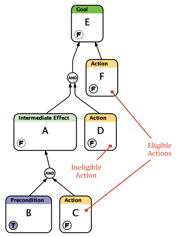
3.Because Preconditions are supposed to be facts about the world, set each Precondition entity’s confidence value to True.
4.Notice that your Solution by itself is sufficient to cause additional effects, so set its confidence value to True and notice how those effects become true.
5.Notice that some of your Actions are “paired up” by AND junctors with other entities that are now True. These Actions are eligible for execution, while other Actions that are paired up with any entities that are not already True are ineligible for execution: they must wait until the other necessary conditions become True.
6.Continue step-by-step through the diagram, telling yourself the “story” of the diagram as you set each Action to True when it becomes eligible, until your Desirable Effects also become True. Correct any errors you discover in your logic along the way.
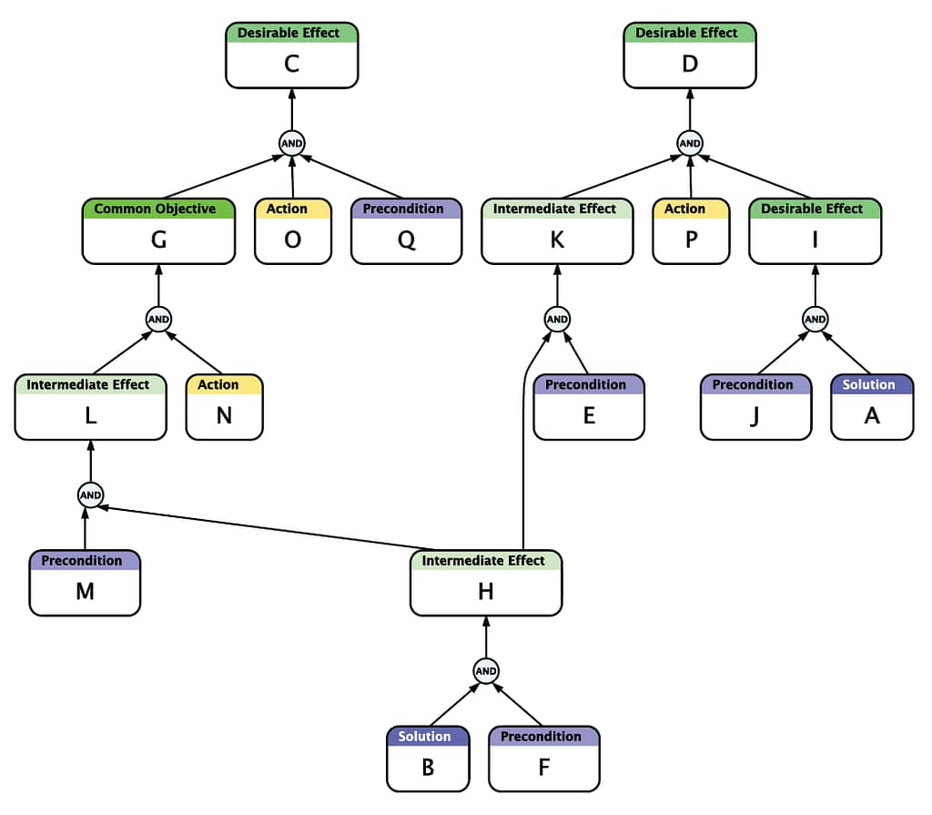
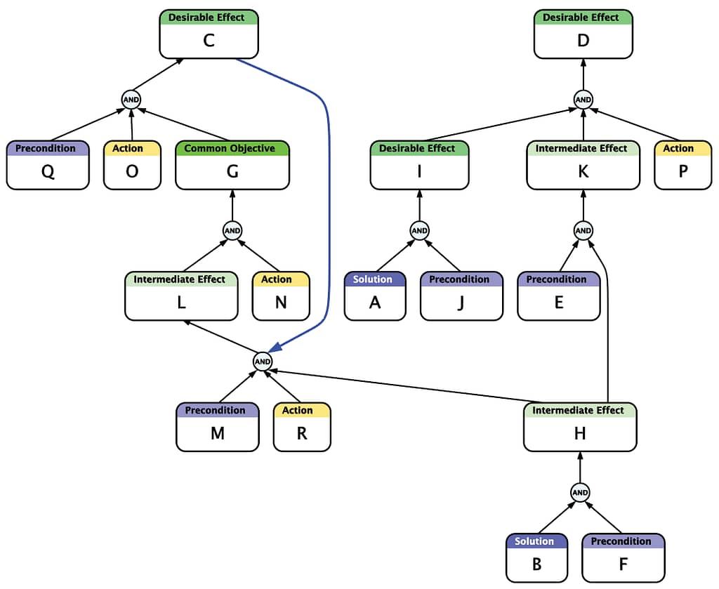
Step 5: Build In Positive Reinforcing Loops
Recall that when building a Current Reality Tree, occasionally there are Un-Desirable effects that are so severe that they “feed back” on others and create negative reinforcing loops. When creating a FRT, you want to look for opportunities to do the opposite: build in positive reinforcing loops. If you can do so, you are more likely to create a solution that is self-sustaining.
Look for Desirable Effects that may intensify effects lower in the tree that lead back to one or more Desirable Effects. If you find such cases, annotate them using Back Edges. Pay close attention to where you might need to add additional Actions in order to create sufficient cause for a positive reinforcing loop’s existence.
Step 6: Seek and Address Negative Branches
This is a critical step. Whether or not you’ve already added some Un-Desirable Effects to your FRT, now is the time to go back over it and carefully search for other UDEs that are consequences of any of the entities we have added.
Once you have done that, look for the earliest places in the causal chain where UDEs start to appear. These “turning points” are the start of Negative Branches. It is critical that you deal with Negative Branches in order to avoid creating worse problems than those you set out to cure.

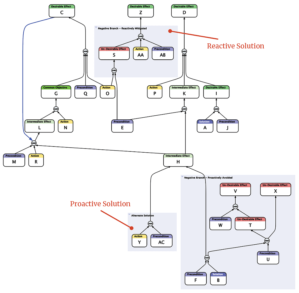
There are two approaches to addressing Negative Branches: Reactive and Proactive.
In the Reactive approach, UDEs are allowed (perhaps even expected) to occur, but are deemed unavoidable. New Action entities (injections) are then paired with the UDEs (along with other entities as necessary) to cause additional effects that mitigate the UDEs. These additional effects are hopefully Desirable Effects, but can also be neutral Intermediate Effects.
In the Proactive approach, alternative injections are created that achieve the next stage of Intermediate Effects that are on the path to the final Desirable Effects, without causing the UDEs. This is also known as “trimming the Negative Branch.”
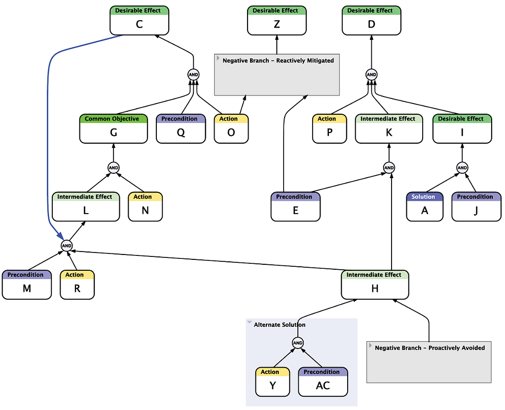
In the illustration below, we deal with one Negative Branch proactively by discarding one of our original Solution entities B and devising an alternate course of action Y. The other negative branch is handled reactively by devising a new Action AA that mitigates the UDE S if and when it occurs.
Once a better path has been created, it is a good idea to keep a record of the entities that participated in the Negative Branch by keeping them in collapsed groups, instead of deleting them.
When someone brings you a well-intentioned proposal that you have concerns about, it is good practice to ask for some time to think about it, then take their proposal and construct a FRT with their suggestion as the initial injection at the root, and with the Desirable Effects predicted by the suggester and the UDEs you foresee as the final outcome. Once you have this FRT, you can discuss it in detail with the suggester. If you or they can develop injections that address the UDEs, then you are likely to have a proposal you can approve.
What’s Next?
Wanting to do more with Flying Logic? You may want to check out these articles:
How to Create a Prerequisite Tree